5 Phase Stepper Motor Driver Projects
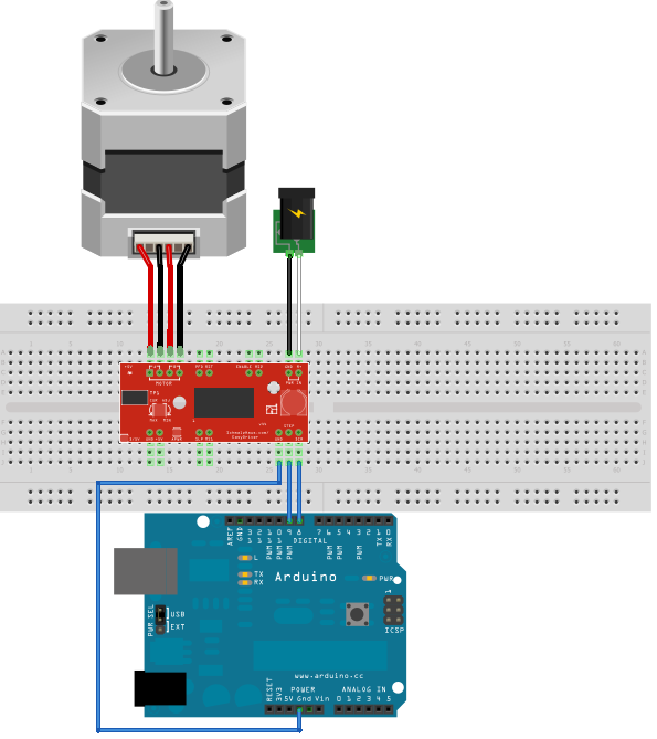
Recently, I was given two Step Syn 103-7515-5042 stepper motors (don't google it, you won't find anything.). They have 10 wires (two per stepper coil), and with some research, I found out they are 5-phase bipolar steppers. They are rated for: 1.4A at 3.22V 0.72째/step NEMA23 Now, I thought I'd design my own 5 phase bipolar stepper driver using 5 H-bridges and an AVR. I already looked at the L298 and the DRV8844. I think the DRV8844 is a better choise for me, as it has a built-in 3.3V regulator to power my AVR. The only problem I have is limiting the current to maximum 1.4A.
Fake driving license uk with hologram. First, I thought of using a 3.3V supply so I don't need current limiting, but at this low voltage the H-bridge IC's won't work. I could use PWM, but then I have no idea where to put my current sensing resistors (because the polarity changes with the H-bridge), and that would require an AVR with 10 PWM channels. Maybe it will be better to use a power resistor in series with the stepper windings. I have a 15V power supply laying around somewhere that could be used with a 10 ohm - 15W power resistor in series with each coil so that we would get approx. What would you think I should do? Sanyo Denki is one of the not-so-nice companies that documentation for their hardware is really difficult to find in some cases. Anyway, you obviously have one of their 5 phase steppers with all coil end brought out.
5-Phase stepper motor drivers that operate in the pulse input mode and built-in controller mode are available. You can select a desired combination according to.
That gives you possibilities in principle, though in practice you may end yp doint it the 'normal way' anyway. 5 phase steppers as a rule are connected in pentagon, where the stator coils form a ring with taps between each coil.
These taps are driven by half-bridges (not H-bridges) and there are 5 of them. There are two fundamental excitation sequences - full steps at 4ex and 5ex and half steps at 4-5ex. The excitation sequences are easily generated with a small CPLD but why not a MCU as well. Current limiting can be either complex or simple. The simple alternative is to measure the combined return current from all half bridges. The current is shared between (typically) 4 coils and assuming the coils are reasonably similar, there won't be big variations in individual coil currents. The low nominal coil voltage is what usually throws people.
That only means that you get nominal current with that DC voltage, but it has little significance in actual usage. The coil inductance will resist current rampup and you need a significantly higher voltage to drive a useful current throug the coils at max working speeds. A rule of thumb is that your supply voltage should be 32 * sqrt(L) volts, where L = coil inductance in millihenries. At those voltage levels you do need a current limiting scheme to keep the coils from cooking at slow speeds, usually a pwm + setpoint vs actual current comparator. Sanyo Denki is one of the not-so-nice companies that documentation for their hardware is really difficult to find in some cases. Anyway, you obviously have one of their 5 phase steppers with all coil end brought out.
That gives you possibilities in principle, though in practice you may end yp doint it the 'normal way' anyway. 5 phase steppers as a rule are connected in pentagon, where the stator coils form a ring with taps between each coil. These taps are driven by half-bridges (not H-bridges) and there are 5 of them. There are two fundamental excitation sequences - full steps at 4ex and 5ex and half steps at 4-5ex. The excitation sequences are easily generated with a small CPLD but why not a MCU as well. Current limiting can be either complex or simple.
The simple alternative is to measure the combined return current from all half bridges. The current is shared between (typically) 4 coils and assuming the coils are reasonably similar, there won't be big variations in individual coil currents. The low nominal coil voltage is what usually throws people. Manfaat sistem informasi perpustakaan berbasis web. That only means that you get nominal current with that DC voltage, but it has little significance in actual usage. The coil inductance will resist current rampup and you need a significantly higher voltage to drive a useful current throug the coils at max working speeds.

A rule of thumb is that your supply voltage should be 32 * sqrt(L) volts, where L = coil inductance in millihenries. At those voltage levels you do need a current limiting scheme to keep the coils from cooking at slow speeds, usually a pwm + setpoint vs actual current comparator. I actually have 5-phase pentagon drivers laying around. I tried them (didn't work), but then I read somewhere else these could only be used in unipolar mode. My steppers are bipolar (thus they have 10 leads instead of 5), and they are internally completely different wired then the unipolar ones.